Z-Rack Nesting Failures: Backroom Space Traps to Avoid
Rolling Z-rack nesting compatibility is controlled by geometry, not by the fact that two racks carry the same name.
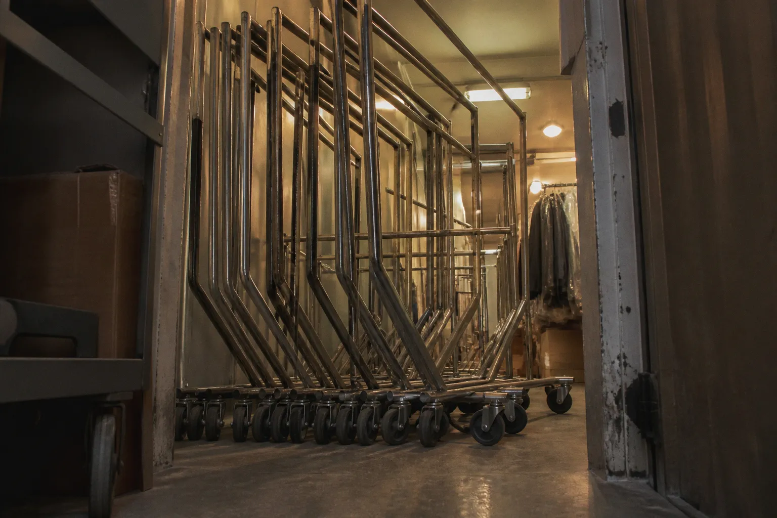
A commercial Z-rack with a nominal 5-foot base may measure approximately 63 to 63.5 inches in length and 23 to 24 inches in depth, yet still fail to nest with another rack built to similar dimensions. The obstruction may be only a caster bumper, a lower crossbar, a weld projection, or an upright rail positioned several millimeters outside the expected path.
This is the main backroom storage error: treating the Z-shaped base as a universal interface. It is not. The angled base creates the nesting function, but the complete clearance profile includes the base angle, caster envelope, wheel offset, hangrail position, uprights, braces, and any add-on hardware. One incompatible component is sufficient to convert a compact stack of empty racks into a row of isolated floor obstacles.
The Mechanics of Z-Rack Nesting Efficiency
A standard Z-rack uses an offset diagonal base rather than a centered rectangular frame. When empty, one rack can slide into the open geometry of another. The result is a reduced rolling garment rack storage footprint in a stockroom, staging area, receiving corridor, or apparel processing zone.
The space saving comes from longitudinal overlap. The racks do not become physically smaller. Their individual base lengths remain approximately 60 to 63.5 inches, depending on the construction. The nested group occupies less floor length because the diagonal bases share the same zone rather than standing end to end.
That distinction matters when calculating backroom capacity. The relevant measurement is not the length of one rack multiplied by the number of units. It is the total length of the nested group, including the clearance required to insert and remove each rack. This clearance must account for:
- the outermost caster wheels and rubber bumpers;
- the turning radius required to align the rack with the nested row;
- the usable aisle width beside the rack;
- the projection of garments, cartons, or polybags beyond the hangrail;
- the height and position of any double-rail assembly;
- the clearance around doors, fire equipment, electrical panels, and egress routes.
A rack can nest tightly in a factory photograph and still perform poorly in a real backroom. The operator approaches at an angle. The floor may have joints or threshold transitions. The casters may not swivel in the same direction. The rack may carry residual garments on one side. The theoretical footprint then becomes an operational footprint.
The 23 to 24 inch base depth is also not the full working width. A 5-inch caster with a bumper can extend beyond the nominal frame. A wheel brake pedal can become the first contact point against the adjacent rack. If the bumper is made from non-marring rubber, it may compress under contact, but this does not eliminate the mechanical interference. It only delays the point at which the force transfers into the frame.
Z-rack nesting is a clearance problem with a load-bearing frame attached to it. The nesting path must be verified as a complete assembly, not as a base shape.
The nesting function should therefore be evaluated in two conditions:
1. Insertion condition. The rack is pushed into the row. Caster swivel, bumper contact, upright alignment, and lower-frame interference determine whether the movement is possible.
2. Stored condition. The rack is fully inserted. The remaining clearance determines whether the units can be removed without lifting, twisting, or striking the adjacent frames.
These are different tests. A rack may enter the row but become trapped because its casters rotate against the wrong edge. A rack may also store correctly while empty but fail to remove after a lower garment bar or accessory frame has been installed.
Anatomy of a Nesting Failure: Why Racks Do Not Align
Commercial Z-rack nesting problems usually originate from a mismatch between nominal dimensions and functional dimensions. Product listings often identify the base length, base depth, rail height, and load capacity. Those values do not fully describe the nesting envelope.
The most frequent failure points are concentrated in five areas.
1. Base angle and diagonal offset
The Z-shaped base must provide an open path for the next rack. If the diagonal member is positioned too far inward, the opposing caster or upright can contact it before the rack reaches its intended position. If it is positioned too far outward, the rack may technically nest but occupy more space than expected.
Two bases can have equal overall length and depth while using different diagonal angles. Their contact points will not coincide. This is why a z rack base dimensions comparison must include the location of the diagonal members, not only the maximum external measurements.
The weld zone is another variable. A fillet weld, gusset, or reinforcing plate can extend into the clearance path. Budget frames may have inconsistent weld geometry from one unit to another. The difference may be small in a static measurement but significant when the caster bumper is already within a narrow gap.
2. Caster diameter and bumper envelope
Commercial Z-racks commonly use 4-inch or 5-inch heavy-duty swivel casters. The diameter affects floor clearance and rolling behavior. The total caster envelope includes more than the wheel:
- wheel width;
- swivel plate;
- mounting hardware;
- brake mechanism;
- bumper ring or external guard;
- lateral offset from the frame.
A 5-inch caster may roll more effectively across floor joints than a smaller wheel, but its swivel plate and bumper can reduce nesting clearance. The bumper is frequently the first component to meet the neighboring rack. It can obstruct nesting even when the base rails themselves would pass.
Caster placement also affects the approach angle. If the front and rear casters are offset differently from the base rails, the rack may require a precise alignment before it can slide into the row. A difference in wheel centerline of only a small amount can force the operator to reposition the rack manually.
Locking casters create a separate failure mode. Most heavy-duty commercial configurations use four swivel casters, often with two locking brakes. If one brake is engaged during insertion, the rack pivots around the locked wheel rather than tracking with the row. The operator may apply more force, increasing the load at the caster plate and base welds.
3. Upright rail interference
The vertical uprights define the upper clearance profile. On adjustable systems, the posts may extend from approximately 70 inches to 85 inches. The height itself does not normally determine whether bases nest, but the post position and hardware can obstruct the adjacent rack.
Push-button adjustment holes, collars, retaining pins, and external sleeves can project from the upright. A double-rail configuration can place a lower hangrail directly in the path of the next rack’s upright. The problem is not limited to the rail tube. End fittings and mounting brackets can create a wider interference zone than the nominal 1-1/4 inch steel tubing.
If the upright is mounted at a different longitudinal position from the reference design, the racks may pass at one height and collide at another. This occurs when a manufacturer uses the same base for several frame configurations but changes the location of the vertical post or lower brace.
4. Lower crossbars and braces
The lower frame is often modified to increase stiffness or support a second hanging level. That modification can eliminate the open space required for nesting. A crossbar may not be visible in the top or front dimensions listed by the supplier, but it can block the diagonal entry path.
This is especially common with add-on double-bar systems. A lower hangrail can extend beyond the intended frame line. When the rack is empty of garments, the hardware remains. The racks no longer have the same clearance profile as the original single-rail version.
Nesting compatibility must therefore be checked after all accessories are installed. A rack that nests in its base configuration does not automatically nest after the addition of:
- a second hangrail;
- shelf brackets;
- side extensions;
- end stops;
- garment separators;
- lower support bars;
- sign frames or merchandising attachments.
5. Frame distortion under load
A loaded garment rack is not a rigid measuring fixture. A 400 to 450 lb rated rack may carry a substantial hanging load along the main rail. The rail can deflect. The vertical posts can rotate slightly under eccentric loading. The casters can develop a different contact pattern on the floor.
Nesting should not be performed with garments still on the racks unless the system is specifically designed and cleared for that operation. The diagonal bases require free movement, and the hanging load can shift the center of gravity. Garments must be removed or sufficient clearance must be maintained before the racks are nested.
A rack that nests only after force is applied is not compatible in operational terms. Force is being transferred into the casters, base welds, or upright connections. Repeated loading can accelerate fatigue at those points.
Critical Base Dimensions and Caster Interference
The base dimensions provide the first screening test for nesting, but they are not the final decision. The following values describe a common heavy-duty commercial range:
| Parameter | Typical commercial range or feature | Why it affects nesting |
|---|---|---|
| Base length | Approximately 60 to 63.5 in | Determines longitudinal overlap and stored row length |
| Base depth | Approximately 23 to 24 in | Defines lateral clearance and aisle demand |
| Rated load | Approximately 400 to 450 lb | Influences frame deflection and caster loading |
| Hangrail tube | Approximately 1-1/4 in steel tubing | Controls rail stiffness and accessory projection |
| Caster diameter | 4 in or 5 in | Affects wheel envelope, floor clearance, and swivel behavior |
| Upright height | Approximately 70 to 85 in adjustable | Changes upper clearance and accessory position |
| Brake configuration | Commonly two locking casters | Can restrict alignment during insertion |
The correct comparison is between the complete external envelope of the racks. Measure from the furthest point of one caster bumper to the furthest point of the opposing base member. Then identify the narrowest internal path through which the next rack must travel.
A practical dimensional review should record:
- overall base length, including bumper projection;
- maximum base width at the caster assemblies;
- center-to-center distance between front and rear casters;
- diagonal base angle or the coordinates of its endpoints;
- position of each upright relative to the base ends;
- lower crossbar elevation and projection;
- clearance between the main rail and the neighboring upright;
- brake pedal position;
- weld beads, gussets, and end caps that extend into the path.
The measurement should be taken on an assembled rack, not from a product diagram alone. Product drawings may show nominal tube dimensions without showing the real external envelope created by welds, wheel plates, and bumpers.
Why identical base lengths do not guarantee compatibility
Suppose two racks both use a base listed as approximately 63 inches long and 24 inches deep. That does not establish a common nesting interface. One may place its rear caster 2 inches closer to the diagonal rail. The other may use a wider rubber bumper. A third may use a lower crossbar extending across the open side.
The result is a dimensional conflict despite apparently matching specifications.
Cross-brand nesting should therefore be treated as unverified unless the manufacturer states compatibility for the exact models. The absence of an explicit incompatibility warning is not evidence of interchangeability. Universal nesting claims are especially weak when the supplier does not publish caster width, bumper projection, upright coordinates, or accessory clearance.
The controlling dimension is the smallest clearance in the nesting path. Overall rack length is secondary.
Floor conditions add another variable. A 4-inch caster can pass over minor surface irregularities, but a threshold, expansion joint, or damaged concrete edge can rotate the wheel assembly and change the rack’s path. When the clearance between frames is small, this wheel deflection is enough to create contact.
The Impact of Add-On Rails on Storage Footprint
Double-rail Z-racks increase hanging capacity by using a second rail or an adjustable lower rail. They also alter the rack’s interference profile. The change may be acceptable in an operating aisle and unacceptable in a nested storage row.
A lower rail can interfere with the upper or vertical assembly of the adjacent rack. Its mounting brackets may extend beyond the nominal base width. If the rail is height-adjustable, the lowest permitted position may be the most problematic because it aligns with the other rack’s diagonal frame or caster plate.
The main issues are mechanical:
1. Rail projection. The lower rail extends beyond the upright centerline and reduces side clearance.
2. Bracket width. The rail support may be wider than the 1-1/4 inch tube.
3. Adjustment hardware. Push-button collars and retaining mechanisms add local projections.
4. Garment envelope. Clothing on the lower rail can extend into the path even when the steel structure clears.
5. Removal sequence. The rack may enter the row only if approached from one direction, creating a practical access failure.
Height adjustment from approximately 70 to 85 inches is useful for apparel handling, but it should not be confused with a nesting feature. A taller upright does not compensate for a lower rail blocking the base path. Likewise, raising the rail may provide upper clearance while creating a new collision with the adjacent rack’s hangrail.
Before adopting a double-rail system, compare the single-rail and double-rail storage conditions. The relevant question is not how many garments the rack holds in isolation. It is how much floor area the loaded operating row and empty backroom stack require after the additional hardware has been installed.
For a stockroom with frequent rack deployment, a lower-capacity rack that nests reliably may provide more usable storage than a higher-capacity rack that cannot be compacted. This is a layout calculation, not a preference. The rack must be evaluated against the number of units stored, the retrieval frequency, and the available turning space.
Structural Integrity Risks in Budget Nesting Systems
Nesting failures are not limited to lost floor space. Repeated interference creates structural stress at locations that were designed to carry vertical and rolling loads, not impact loads.
The most exposed components are the caster mounting plates, base welds, diagonal frame joints, and main hangrail. Common failure reports for non-standard or budget Z-racks include base weld breakage, bending of the main hangrail tube, and structural collapse. These failures are consistent with a system subjected to force outside its intended load path.
Base welds
The diagonal base transfers the load from the uprights toward the casters and floor. If an operator pushes a misaligned rack into another unit, the contact force can act laterally at the end of the diagonal member. The weld then receives a load that is not equivalent to the vertical garment load.
Repeated lateral impacts can initiate cracking at the weld toe. Corrosion can accelerate the process if the protective coating is damaged. A zinc-plated surface offers sacrificial corrosion protection, but it does not restore a cracked weld or prevent mechanical fatigue.
Main hangrail
The main rail is commonly fabricated from approximately 1-1/4 inch steel tubing. Its capacity depends on tube wall thickness, span, support spacing, steel grade, and load distribution. A rail with a heavy nominal load rating can still bend when garments are concentrated at the center or when the frame is moved over uneven flooring.
A bent hangrail changes the upper clearance profile. It may sag into the path of an adjacent rack. The deformation also shifts the hanging load, increasing eccentricity at the uprights. If the rail is already bent, nesting contact should not be used as a method of straightening it.
Casters and mounting plates
Caster impact is transferred through the swivel plate and fasteners into the base. A 5-inch caster may improve rolling over rough surfaces but can generate greater leverage at the mounting connection when the wheel strikes an obstruction. Locking mechanisms can further concentrate the load when a brake is engaged during movement.
The wheel should roll. It should not be dragged sideways against a bumper while the rack is under load. Side loading increases the chance of swivel deformation and fastener loosening.
Coatings and corrosion
Garment storage systems are often exposed to lint, cleaning chemicals, moisture from loading areas, and abrasion from repeated contact. Zinc-plated components and epoxy-polyester powder coatings provide different protection mechanisms. Zinc plating uses a sacrificial metallic layer. Epoxy-polyester systems provide a barrier coating with resistance determined by surface preparation, film thickness, chemical exposure, and impact damage.
The coating does not determine nesting compatibility. It determines how the frame responds after contact and exposure. A sharp bumper strike can chip the coating at a weld or tube edge. Once the steel substrate is exposed, moisture and chemical residues can initiate corrosion. In humid stockrooms, the damaged area should be inspected rather than covered with an arbitrary paint layer.
For environments with routine washdown, corrosive cleaning agents, or outdoor staging, material and coating selection must be specified separately from the rack geometry. A compatible stainless or corrosion-resistant construction may be justified in a severe environment, but it still requires a compatible base and caster profile. Corrosion resistance cannot correct an incorrect nesting path.
A Forensic Test for Rolling Z-Rack Nesting Compatibility
The most reliable evaluation is a physical clearance test using the exact rack configuration intended for deployment. The test should not be performed with a generic single-rail sample if the operation will use double rails, extensions, or accessory brackets.
Use the following sequence:
1. Assemble both racks completely. Install the casters, bumpers, rails, adjustment hardware, braces, and accessories specified for operation.
2. Record the external envelope. Measure the maximum base length and depth, including wheel and bumper projections. Record upright and crossbar positions.
3. Inspect the open nesting path. Identify the narrowest gap between the diagonal base, caster assembly, lower rail, and upright.
4. Release all caster brakes. Test the rack with the wheels free to swivel. Repeat the test with the intended brake procedure to determine whether operators can align the unit without excessive force.
5. Insert one empty rack into another. Use normal push force. Do not lift the frame or strike it against the stored rack.
6. Repeat the movement several times. A single successful insertion does not establish repeatable compatibility. Watch for caster rotation, bumper compression, and contact at welds or brackets.
7. Test the reverse movement. The rack must be removable without binding. Retrieval is part of the nesting function.
8. Test the loaded operating condition separately. Do not nest loaded racks unless the manufacturer provides a procedure and the clearance remains sufficient for the actual garment load.
9. Inspect contact points. Look for coating damage, bent bumper hardware, loose caster fasteners, weld cracking, and rail deformation.
10. Document the configuration. Record model numbers and accessory combinations. Compatibility may apply to one version and fail after a rail or brace change.
The test should be repeated on the actual floor surface. A smooth showroom floor is not a substitute for a stockroom with thresholds, floor joints, or localized damage.
If the rack requires lateral impact to complete insertion, classify the configuration as incompatible. If operators must lift one side, the caster system is not providing the intended rolling function. If the rack can enter only from one direction, mark the required direction and verify that the backroom layout preserves that approach path.
Choosing Between Compact Nesting and Higher Load Capacity
The nominal capacity of 400 to 450 lb is relevant only when the complete frame, rail, caster system, and floor condition support the load. It does not indicate how efficiently the empty units store. Capacity and nesting are separate performance variables.
A high-capacity rack is appropriate when:
- the garment load approaches the rated range;
- the rack remains stationary or moves infrequently;
- the rail span and support structure limit deflection;
- the floor can support the caster load;
- the backroom has sufficient space for non-nested storage when required.
A compact-nesting rack is appropriate when:
- empty units must be returned to a narrow staging zone;
- the deployment cycle requires frequent removal and re-storage;
- the rack configuration is standardized across the fleet;
- caster and bumper dimensions are documented;
- the nesting test passes with all operating accessories installed.
A system that combines both requirements can be specified, but the supplier must provide more than a load rating. Request the assembled base dimensions, caster envelope, rail positions, adjustment range, and approved nesting configuration. If these values are unavailable, physical validation becomes mandatory.
The same rule applies when replacing an existing fleet. A new rack may fit the floor plan as a single unit and fail as a replacement because its diagonal base, bumper, or upright position differs from the old model. Mixing generations in one nesting row is a high-risk arrangement. The difference may not be visible until the units are pushed together.
Definitive Specification Rule
For commercial garment storage, select the rack by the controlling failure mode.
If the primary requirement is heavy hanging capacity, specify the load path first: steel tube gauge, rail span, upright connection, base weld construction, caster rating, and floor condition. Then verify that the loaded frame does not deflect into adjacent traffic space.
If the primary requirement is backroom compression, specify the nesting geometry first: base length, base depth, diagonal angle, caster diameter, bumper projection, upright position, and accessory clearance. Then verify removal as well as insertion.
Do not approve a mixed fleet on the basis of similar dimensions. Do not assume that all commercial Z-racks nest across manufacturers. Do not nest fully loaded racks unless the configuration is explicitly designed for that operation. Do not treat a damaged coating, bent rail, cracked weld, or loose caster as a cosmetic defect. Each is evidence that the frame has experienced a load or contact condition outside the intended path.
The definitive selection rule is simple: use nesting Z-racks only when the complete assembled envelope is compatible, and use the rated load only within the structural and environmental limits of the frame. Base shape creates the opportunity for compact storage. Precise geometry determines whether that opportunity survives contact with the backroom.