LED garment racks: power and wiring prep checklist
The most common failure in a backlit wardrobe rail is not the LED strip itself. It is the planning around it.
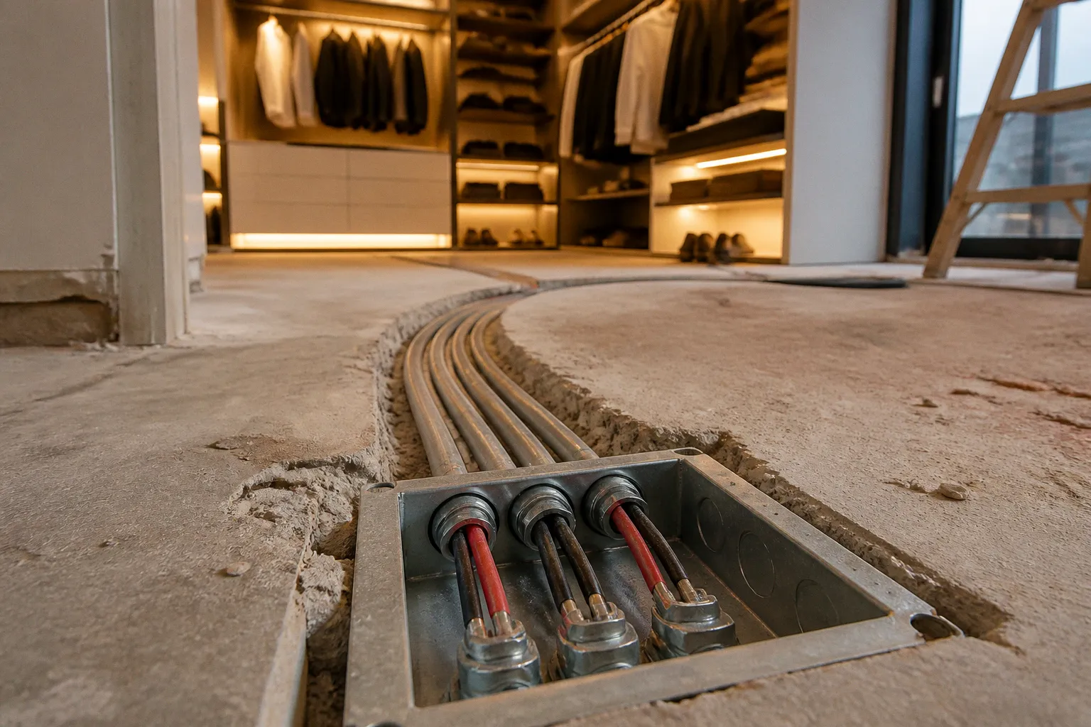
A short strip works perfectly on a workbench, then looks uneven once it is stretched across a long garment rack, routed around a corner, and connected with the thin cable supplied in the box.
The usual pattern is predictable: the strip is bought first, the power supply is treated as an accessory, and the wiring is figured out after the rail is already mounted. That order makes a clean installation much harder than it needs to be. The reliable version starts with voltage, total load, wire length, connection points, and access to the driver.
A backlit garment rack is only as good as the wattage and wiring decisions made before the first strip is mounted.
This is not glamorous work. Nobody shows the power calculation in the finished closet photograph. But it determines whether the far end of the rack stays bright, whether the driver runs comfortably, and whether a future repair means removing one cover or opening a wall.
Voltage Selection: 12V vs 24V Systems for Closet Displays
LED strips and illuminated garment rails normally operate on low-voltage direct current rather than the 120V AC used by a North American household circuit. The driver converts the incoming line voltage to the DC output required by the rack or strip. In residential display work, the two operating voltages most often encountered are 12V DC and 24V DC.
The choice affects more than the label on the power supply. It changes the current in the circuit, the sensitivity to voltage drop, the practical wire size, and the way a long rack should be fed.
For the same wattage, a 24V system draws about half the current of a 12V system:
- A 48W load at 12V draws approximately 4A.
- The same 48W load at 24V draws approximately 2A.
That lower current is useful because resistance in the cable produces a voltage drop. The longer the run and the higher the current, the more noticeable that drop becomes. The result may be a gradual reduction in brightness, a color shift on some tunable or RGB products, or inconsistent performance when several sections turn on together.
The difference is often minor on a short single-rail installation. It becomes more important when the rack spans a long wall, the cable has to travel up and over a door opening, or several rails and shelf sections share one driver.
| Parameter | 12V DC system | 24V DC system |
|---|---|---|
| Current for the same wattage | Higher | Lower |
| Sensitivity to cable voltage drop | Greater, especially on long runs | Lower for the same wattage and cable length |
| Typical fit | Short rails, compact displays, some ready-made kits | Longer rails, multiple sections, higher-output systems |
| Component compatibility | Must use 12V-rated strips, controls, and driver | Must use 24V-rated strips, controls, and driver |
| Wiring tolerance | Requires more attention to gauge and feed points | More forgiving, but still requires calculation |
| Main limitation | More current through the same cable | Components may cost slightly more or be less common in basic kits |
Voltage is not interchangeable. A 12V strip connected to a 24V driver can be damaged quickly. A 24V strip connected to a 12V driver may remain dark or operate incorrectly. The output marking on the strip, controller, and driver must agree before anything is connected.
When 12V still makes sense
A 12V system is not automatically the wrong choice. It can be practical when the rail is short, the LED product is already designed as a complete 12V kit, and the driver can be placed close to the load. It is also common in compact wardrobe accessories and small display fixtures where the total wattage is modest.
The problem begins when a short-run product is stretched into a long installation without changing the wiring plan. The supplied lead may be adequate for the original design length but not for a much longer extension. A 12V setup can work well across a garment rack, but it may need a larger conductor, shorter branch circuits, or power injection at more than one point.
When 24V earns its place
For a long closet wall or a rack with several illuminated sections, 24V often simplifies the installation. Lower current reduces the voltage lost in the cable and gives the designer more flexibility in placing the driver. It does not eliminate voltage drop, and it does not make undersized cable acceptable. It simply starts with a more favorable current level.
The length limits printed by a manufacturer should be treated as part of the design, not as universal laws. A strip’s maximum run depends on its wattage per unit length, copper layout, LED arrangement, feed method, and the amount of brightness uniformity the manufacturer is willing to guarantee. One product may tolerate a longer single-end run than another product with the same nominal voltage.
For a long garment rack, check four things together:
1. The strip or rail voltage.
2. The total wattage of every connected section.
3. The recommended maximum run and feed method.
4. The voltage drop calculated for the actual cable length and gauge.
If the system is not yet purchased, 24V is often the cleaner starting point for a multi-rail installation. If the system is already 12V, the answer is not necessarily replacement. It may be a matter of shortening branches, feeding from both ends, increasing conductor size, or splitting the load across separate outputs.
Calculating Power Supply Capacity and the 80% Rule
Power supply sizing is where many lighted clothes rack setups go sideways. The calculation is simple, but only if the load is measured honestly.
Start with the actual power requirement of the connected LED product. If a strip is rated at 4W per foot and the installation uses 12 feet, the nominal LED load is 48W. If the rail includes an integrated controller, dimmer, sensor, or RGBW electronics, account for the consumption of those components as well. A controller may be small compared with the LEDs, but it still belongs in the system calculation.
The basic formula is:
Total load = length of each LED section × rated wattage per unit length, added across the entire installation
For multiple sections:
Total load = section 1 + section 2 + section 3 + controller and accessory allowance
The rating should come from the product specification rather than the product title. Marketing language such as “high output” or “extra bright” does not tell you how much power the rail requires. If the listing does not provide wattage per foot, wattage per metre, or total input power, the installation is being designed with incomplete information.
What the 80% figure actually means
A common design practice is to avoid operating a power supply continuously at its full nameplate rating. An 80% loading target gives the driver thermal and performance headroom. It is a sizing convention and a conservative engineering margin, not a universal statement that every electrical code applies an 80% rule to every low-voltage LED driver.
Whether a specific installation is subject to a code requirement depends on the equipment, wiring method, location, and jurisdiction. The driver’s listing and installation instructions also matter. Do not present the 80% calculation as a substitute for checking the applicable rules.
For design purposes, the calculation can be written this way:
Minimum nominal driver capacity = total calculated load ÷ 0.8
A 48W load therefore points to a driver with at least 60W of rated capacity when using the 80% design target. That does not mean every 48W LED system legally requires a 60W driver. It means a 60W unit provides the selected operating margin, assuming the driver is compatible with the load and installed according to its instructions.
| Calculated LED load | Driver capacity using an 80% design target | Practical consideration |
|---|---|---|
| 24W | 30W or larger | Suitable for a small, short rail if the driver is properly rated |
| 48W | 60W or larger | Leaves room for thermal headroom under the design method |
| 80W | 100W or larger | Check driver enclosure, ventilation, and cable capacity |
| 120W | 150W or larger | Consider splitting long runs across branches |
| 160W | 200W or larger | Confirm controller rating and plan service access carefully |
These are sizing examples, not a replacement for the manufacturer’s instructions. A driver must match the system voltage and provide the required output type. A larger wattage rating is not automatically better if the driver is poorly made, physically unsuitable, or incompatible with the controller.
Why more capacity is not always the answer
Oversizing has a useful role, especially when a second garment rail or shelf section may be added later. But there is a difference between leaving reasonable headroom and buying a much larger driver without checking the rest of the circuit.
The LED load determines the current drawn in normal operation. A 200W constant-voltage driver does not force a 48W LED load to consume 200W. The load draws what it requires at the driver’s voltage, provided the driver can supply it. The larger unit may run with more unused capacity, but the cable, terminals, switches, connectors, and controller still need to be suitable for the actual circuit.
That distinction matters when diagnosing dimming. If the lights are dim at the far end, replacing a 60W driver with a 200W driver may do nothing if the original driver already had enough capacity. The cause may instead be cable resistance, a poor connector, an excessively long branch, or a feed arrangement that leaves too much current traveling through one section of wire.
A larger driver provides capacity; it does not repair a voltage-drop problem in the cable.
Before ordering the driver, record:
- The rated voltage of the LED rail or strip.
- The wattage per foot or metre.
- The total illuminated length.
- The current rating of any dimmer, sensor, or controller.
- The planned branch and extension lengths.
- Whether the driver will be enclosed or installed in a ventilated location.
- Whether the driver will remain accessible for replacement.
If the installation may expand, reserve capacity deliberately. Do not assume that a future section can simply be connected to the nearest existing wire. The extra load may exceed the controller rating or turn a reasonable branch into a long, high-current run.
Selecting the Right Wiring: Why Stranded Copper Matters
The cable included with an LED kit is often selected for the kit’s original dimensions, not for a custom closet installation. It may be perfectly adequate for a short lead and completely unsuitable once the driver is moved to the top of a cabinet or the far side of a wall.
For many small residential LED extensions, stranded copper is the practical choice because it handles repeated bends and tight routing better than solid conductor wire. The correct gauge depends on current and distance, so “18 AWG for everything” should not be treated as a universal prescription. An 18 AWG stranded copper lead may be appropriate for a modest branch, while a longer or higher-current run may require a larger conductor or a different feed arrangement.
The conductor count follows the lighting type:
- Single-color strips usually need two conductors: positive and negative.
- RGB strips generally need four conductors: one common supply connection and three color channels, depending on the control architecture.
- RGBW strips generally need five conductors: the supply connection plus separate red, green, blue, and white channels, again subject to the manufacturer’s wiring scheme.
- Addressable products may use a different arrangement, commonly including power, ground, and data. Their data-line requirements should come from the product documentation rather than from a generic LED-strip diagram.
Why stranded cable works well around wardrobe hardware
A garment rack creates awkward cable geometry. The lead may need to turn around a mounting bracket, enter a hollow rail, pass through a small cabinet opening, and remain flexible enough that the rack can be serviced later. Stranded cable tolerates those movements better than a rigid solid conductor.
That does not make stranded wire immune to failure. Poorly terminated strands can splay, loosen, or be trapped unevenly under a screw terminal. Use terminals and connectors designed for the conductor type, and avoid forcing a bare bundle into a terminal that expects a ferrule or a solid pin. Where the equipment permits it, a properly crimped ferrule can make the connection more consistent. The terminal should be tightened according to the equipment instructions, not simply tightened until it feels secure.
The key wire-selection factors are:
- Conductor material: Copper generally offers lower resistance than copper-clad aluminium for the same nominal size. Confirm what the product actually uses.
- Gauge: Select it from the expected current and total one-way distance, with voltage drop in mind.
- Number of conductors: Match the strip and controller architecture.
- Insulation and jacket rating: The cable must be suitable for its location, especially if it will be concealed.
- Flexibility: A tight cabinet or rail route favors cable that can bend without stressing the terminals.
- Termination method: Connectors must be rated for the conductor size and expected current.
- Mechanical protection: Edges in metal rails and cabinet panels can cut insulation unless they are protected with a bushing or grommet.
Three common routing approaches
Surface-mounted channel below the rack:
This is the easiest arrangement to inspect and modify. Stranded cable can be placed in a small raceway or wire channel, keeping it away from clothing and hangers. The trade-off is visibility, although a painted or color-matched channel can be unobtrusive.
Inside a cabinet or hollow rail cavity:
This keeps the wiring out of sight but still allows access through a removable back panel or end cap. Secure the cable so it cannot rub against sharp edges or move every time the rack is loaded. Leave enough service loop to remove a connector without pulling on the strip.
Behind finished drywall:
This is the point where cable selection and local requirements become more important. Concealed low-voltage wiring may be subject to rules involving cable listing, protection from physical damage, separation from line-voltage wiring, support, and access to junctions. The fact that a cable carries low voltage does not automatically make every cable type acceptable inside a wall.
If the installation involves opening a wall, routing through framing, or sharing an enclosure with line-voltage conductors, verify the permitted wiring method with the local authority or a qualified electrician before closing the surface. The cheapest time to discover a routing problem is before the drywall goes back.
Managing Polarity and Preventing Voltage Drop in Long Runs
Low-voltage DC wiring has polarity. The positive and negative conductors are not interchangeable, and a reversed connection can keep the strip dark or damage components. RGB, RGBW, and addressable products add more opportunities for a connection to be placed on the wrong terminal.
The familiar red-positive and black-negative convention is useful, but it is not a guarantee. Manufacturers may use different colors, especially on preassembled leads. Read the markings on the strip, rail, controller, and driver:
- The driver output may be labeled V+ and V−.
- The strip may be marked +, −, 12V, or 24V.
- A controller may label its input separately from its output.
- RGB and RGBW terminals may use channel labels rather than simple positive and negative markings.
The strip’s printed legend and the product documentation take priority over the color of a loose cable. Before applying power, use a multimeter to confirm continuity and polarity where practical. This is particularly valuable after making several splices or routing a cable through a hollow rail where the conductors can be visually difficult to follow.
Voltage drop is a layout problem as much as a wire problem
Voltage drop depends on the current, the resistance of the conductors, and the distance the current travels. For a two-wire circuit, the relevant path includes the outgoing and return conductors. A long cable therefore has more resistance than its one-way length alone suggests.
The load current can be estimated from:
Current = watts ÷ volts
That explains why a 12V system carrying a given wattage is more sensitive to cable resistance than a 24V system carrying the same wattage. It also explains why two installations with the same driver rating can require different cable sizes: their loads and cable lengths may be different.
The LED load, not the unused capacity of the driver, sets the normal operating current. A 200W constant-voltage driver connected to a 48W load does not push 200W through the wire. However, if the cable is too small for the load current and distance, its resistance can produce voltage drop and heat in the conductor. A larger driver will not remove that resistance. In some fault conditions, available current capacity may also affect how quickly protective devices or the driver’s own protection responds, which is another reason to use compatible, properly protected equipment.
Ways to reduce the problem
Shorten the branch:
Place the driver closer to the garment rack when the location remains accessible and suitable. A shorter low-voltage run usually means less resistance and less hidden cable.
Use a larger conductor:
Increasing conductor size reduces resistance. This may be less convenient to route, but it can be cleaner than trying to compensate with multiple questionable connectors.
Choose 24V for a new long-run design:
The lower current at the same wattage helps, provided the strip, controller, and driver are all designed for 24V.
Feed the strip or rail from more than one point:
A long strip may be fed from both ends or divided into separate branches. Follow the manufacturer’s instructions because some products do not support every feed arrangement, especially when controllers and color channels are involved.
Split a multi-rail installation into branches:
Instead of sending the entire load through one long path, use an appropriate distribution point or separate outputs. Every branch still needs its own current and voltage-drop check.
Avoid relying on daisy-chain connectors:
Each connector adds resistance and another possible failure point. A neat home-run arrangement may take more cable but can be easier to troubleshoot and more consistent across several rails.
A practical test is to measure voltage at the driver output and again at the far end while the LEDs are operating at their intended brightness. The difference shows whether the cable and connections are consuming a meaningful part of the available voltage. The acceptable range depends on the LED product and the manufacturer’s guidance; the goal is not to chase an arbitrary number but to keep the load within its specified operating range.
If one end is visibly brighter, inspect the feed arrangement before replacing the driver. Check the connectors, terminal tightness, cable gauge, total length, and whether the strip is being asked to carry more current than its layout supports.
Safety Standards for Concealed Low-Voltage Routing
The low-voltage side of a garment rack still needs a proper installation. Low voltage reduces some hazards, but it does not make damaged insulation, inaccessible connections, overloaded terminals, or badly installed line-voltage equipment acceptable.
The driver is the boundary between the household circuit and the rack. Keep the line-voltage input on the equipment side intended for it, and route only the correct low-voltage output toward the garment rail. Do not place household mains conductors inside a hollow metal rail simply because the rail provides a convenient route. The rail may be conductive, may have sharp internal edges, and may be touched while clothing is being moved.
Class 2 is a marking and equipment designation
A driver is not automatically Class 2 merely because its output is below a particular voltage or wattage. Voltage and power alone do not establish that classification. The power supply must be specifically listed, marked, or otherwise identified as Class 2 by the applicable product certification system, and it must be installed within the conditions of that listing.
That distinction matters when selecting a concealed driver. Look for the manufacturer’s actual certification and output markings, not a general assumption based on the numbers printed on the box. A product may be low voltage without carrying the particular listing required for a planned installation.
Local rules may also address the cable, enclosure, junctions, support, accessibility, and separation from line-voltage wiring. A listed driver does not make an unapproved wiring method acceptable.
Separation and protection
Keep low-voltage wiring separated from line-voltage conductors unless the enclosure and wiring method are specifically approved for that arrangement. A shared junction box may require a listed divider or another approved means of separation. Do not assume that simply placing both types of wire in the same box is permitted.
Protect the cable wherever it passes through metal or drilled wood:
- Use grommets or bushings at sharp openings.
- Keep conductors away from screw points and moving brackets.
- Secure the cable so it cannot rub against the rail during normal use.
- Avoid crushing the insulation beneath clamps or cabinet panels.
- Keep connectors out of places where clothing can snag them.
- Make splices in accessible, appropriate enclosures rather than burying them loose inside a wall.
- Leave a service loop near the driver and at removable rack sections.
Cable support intervals should follow the cable manufacturer’s instructions and local requirements. The often-used practice of securing a visible or accessible low-voltage run at regular intervals is sensible, but it should not be presented as a universal code distance for every cable type and installation method.
Keep the driver serviceable
A driver mounted behind finished drywall may work perfectly until it fails. Then the installation becomes a demolition project. Put the driver in a location that remains reachable: the top of an adjacent cabinet, a ventilated closet compartment, an accessible soffit, or another serviceable space may work if the equipment instructions allow it.
Do not bury a driver under clothing, insulation, or a sealed cavity where heat cannot leave. Check the required clearances and mounting orientation. A driver that is technically powerful enough may still be unsuitable if its enclosure becomes too warm in the chosen location.
If the project includes new line-voltage wiring, an inaccessible junction, a shared box, or concealed cable through finished construction, involve a qualified electrician where required. The difficult part is not connecting two low-voltage conductors. It is knowing whether the entire route, enclosure, cable type, and access plan are permitted for that location.
Low-voltage does not mean no-rules. It means the rules concern a different part of the system.
Final Reality Check Before You Buy
The buying decision is where a small amount of preparation saves the most rework. Before ordering an LED garment rack or backlit wardrobe rail, write down the system rather than relying on the kit photograph.
- Confirm whether the product is 12V DC or 24V DC. Do not mix the two.
- Find the actual wattage per foot, wattage per metre, or total input rating in the specification.
- Add every illuminated rail, shelf, sensor, controller, and accessory to the load calculation.
- Use a conservative capacity margin, such as the 80% design target, without treating it as a universal electrical-code rule.
- Confirm that the driver is specifically listed and marked for the intended use, including any Class 2 designation the installation requires.
- Check the current rating of dimmers, motion sensors, RGB controllers, and distribution blocks.
- Select stranded copper cable with a gauge suitable for both the current and the full circuit distance.
- Count conductors before routing: single-color, RGB, RGBW, and addressable systems do not use the same cable.
- Plan where the driver will live and how it will be replaced.
- Decide whether the rack will be end-fed, center-fed, fed from both ends, or split into separate branches.
- Protect every passage through metal or wood with the correct bushing or grommet.
- Keep low-voltage conductors separated from line-voltage wiring unless the equipment and enclosure are approved for that arrangement.
- Verify polarity at the driver, controller, and rail before energizing the system.
- Check the far-end voltage under load if the run is long or the brightness is uneven.
- Confirm local requirements before concealing any cable behind a wall.
The important correction is simple: the driver, wire, and LED rail are one electrical system. A driver with more capacity cannot compensate for a long resistive cable. A thick cable cannot make a 12V strip compatible with a 24V driver. A low-voltage output does not automatically qualify as Class 2. And an 80% sizing margin is a useful design choice, not a magic sentence that replaces the applicable code.
Get those decisions right and the lighting can disappear neatly into the rack while remaining bright, serviceable, and predictable. Get them wrong and the symptoms arrive in the usual order: a dim far end, a warm connector, a flicker that appears only after the closet door closes, and another trip to buy a replacement reel.
The reliable installation is decided before the strip goes on the rail.