Heavy-duty clothes racks: weight capacity traps to avoid
A heavy-duty clothes rack rated at 630 lb may have a practical moving capacity closer to 440 lb. The difference is not a marketing detail.
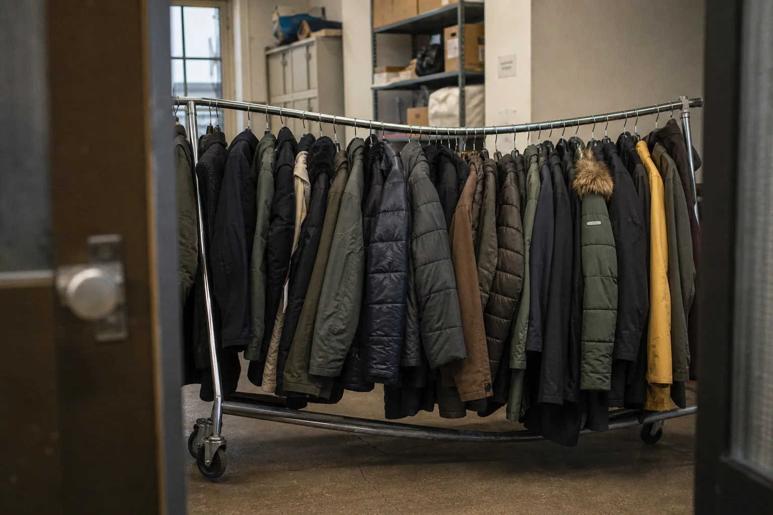
It is the result of lateral stress, rolling friction, uneven loading, and acceleration through turns or over floor joints. A static load rating applies to a rack standing on a level surface. It does not describe the same rack being pushed through a stockroom.
This distinction is the central failure point in heavy duty clothes rack weight capacity limits. Buyers compare the largest number on a product page, then load the rack with garments whose mass is concentrated at the ends or above the caster line. The frame bends, the wheels deform, or the rack becomes unstable before the stated limit is reached.
Commercial clothing rack weight limit claims must therefore be read as structural data, not as a single usable number. The steel section, tube diameter, rail span, connection method, caster assembly, and load distribution determine the working capacity. The printed rating is only one input.
The static versus dynamic load fallacy
Static capacity is measured with the rack stationary. The frame carries vertical force. The casters transmit that force to the floor. On a level surface, the primary stress is compression and bending in the uprights, rails, and joints.
Movement introduces additional loads:
- The rack experiences lateral force when it is pushed or stopped.
- Casters turn at different rates during a change of direction.
- Floor joints and thresholds create short impact loads.
- Garments swing, shifting the center of mass.
- Uneven loading produces torsion across the upper frame.
- Small wheels increase rolling resistance and transmit sharper impacts.
These forces do not need to be large to reduce the usable capacity. A rack rated for 630 lb in a stationary condition may support approximately 440 lb while moving, a reduction of roughly 30% to 40%. The exact dynamic rating is frequently omitted by manufacturers. A product listing that provides only a static number does not establish a safe mobile working load.
A static rating describes a rack at rest. It does not certify the rack as a mobile load carrier.
The distinction is especially severe with rolling garment racks used in retail replenishment, costume departments, laundries, and distribution areas. A stationary rack can tolerate a high vertical load if the frame is properly supported. The same load becomes a moving mass. The operator must overcome inertia, caster friction, and surface irregularities. The frame responds with lateral deflection rather than pure vertical compression.
A rack that remains upright while stationary may still fail operationally. Typical symptoms include:
1. Rail deflection. The hanging bar develops a visible downward curve, usually near the center or at an unsupported extension.
2. Caster misalignment. One wheel begins to track at an angle, increasing resistance and loading the mounting plate.
3. Joint movement. Bolted or inserted connections develop play. The frame begins to rack from side to side.
4. Upright rotation. One side of the rack twists under an uneven garment load.
5. Tipping tendency. The upper load shifts outside the footprint of the caster base during a turn or stop.
For a fixed rack, the static rating is more relevant because movement is absent. For a rolling rack, the dynamic rating should control the procurement decision. When the dynamic value is not published, applying a conservative reduction to the static rating is more rational than treating the advertised figure as a guaranteed mobile capacity.
Steel gauge and tube diameter establish the load path
The frame does not carry weight as an abstract “heavy-duty” category. It carries force through a specific cross-section of steel. Two racks with identical dimensions can have materially different capacity if one uses thinner tube walls or smaller outside diameters.
Domestic and light-duty clothing racks commonly use steel around 0.6 mm thick. Their nominal capacity is often 20 kg to 40 kg, or approximately 44 lb to 88 lb. This is adequate for a limited number of light garments. It is not a reliable basis for dense apparel storage, repeated movement, or long-term loading near the limit. Thin-wall tubing is more vulnerable to local denting at fasteners, ovalization at joints, and permanent bending in long spans.
Commercial and industrial racks more commonly use 0.8 mm to 1.0 mm steel with tube diameters of 1 in, or 25.4 mm, and above. These dimensions support substantially higher loads. Typical commercial heavy-duty capacities fall in the range of 80 kg to 160 kg, or approximately 176 lb to 350 lb, with industrial Z-racks and multi-rod systems reaching approximately 500 lb to 630 lb under stated static conditions.
The increase is not linear. Bending resistance depends strongly on the geometry of the section. A larger tube diameter places more material farther from the neutral axis, increasing resistance to bending. Wall thickness contributes to local stability and resistance to buckling. A large-diameter tube with an inadequate wall can still fail at a connection or under concentrated loading. A thick wall in a small tube can produce a rigid but inefficient section. Both dimensions must be assessed together.
The hanging rail is usually the most highly stressed member because it spans between uprights and carries concentrated hanger loads. A 1.0 mm steel rail can support approximately 109 kg per meter under stated support and distribution conditions. Over a 1.83 m span, the total cited capacity can reach approximately 200 kg when the rail is properly bracketed and the garments are evenly distributed.
That figure cannot be transferred directly to every rack. It assumes an appropriate rail section, adequate brackets, sound uprights, and uniform loading. A rail may possess sufficient bending strength while the base, caster plate, weld, or connector does not. The weakest component controls the assembly.
The relevant construction variables
When comparing a commercial clothing rack weight limit, the following specifications provide more useful information than the phrase “heavy-duty”:
- Tube wall thickness: 0.8 mm to 1.0 mm is a more credible commercial range than 0.6 mm domestic construction.
- Tube diameter: 25.4 mm or larger provides a stronger basis for high-capacity rails and uprights.
- Rail span: Longer unsupported spans increase bending stress and deflection.
- Support spacing: Intermediate brackets reduce the effective span and lower rail deflection.
- Joint construction: Welded steel and mechanically secured metal joints generally provide a more stable load path than thin plastic connectors.
- Surface treatment: Zinc-plated steel resists surface corrosion in dry commercial interiors; coating selection must match humidity and chemical exposure.
- Finish system: Epoxy-polyester coatings provide a different abrasion and corrosion profile from simple plated or painted steel.
- Base geometry: A narrow base raises the tipping risk when the upper rail is fully loaded.
- Caster attachment: The wheel, stem, mounting plate, and frame connection must be treated as one load-bearing assembly.
A product page that publishes only total weight capacity but omits tube thickness and diameter leaves the structural basis incomplete. The number may still be valid, but it cannot be compared directly with a rack whose construction is documented.
Extendable rails create leverage, not free capacity
Adjustable garment racks are useful because they fit changing apparel volumes and storage footprints. The extension mechanism also changes the force distribution. A rail that extends from approximately 129 cm to 189 cm or more has a longer effective span and greater leverage at the ends.
The added length increases bending moment. If the rail is supported only at the uprights, garments placed near the extended ends exert force farther from the support points. The result is higher deflection and greater rotational force at the joints. The rack may also become more sensitive to an uneven load because the center of mass moves away from the centerline.
An extended rack therefore does not retain the same practical capacity as a compact rack unless the manufacturer specifies that condition. The maximum rating may apply only to the shortest configuration, or only to evenly distributed static loading. The extension should be treated as a reduction factor unless test data says otherwise.
The load should remain between the primary uprights whenever possible. End loading is structurally inefficient. It applies force where the rail has less support and increases torsion in the vertical members. A row of dense coats placed at one end can produce more instability than a larger number of lighter shirts distributed across the full span.
Adjustable rails also introduce interfaces. Telescoping sections depend on overlap length, locking holes, clamps, pins, or friction fittings. These parts carry local forces that do not exist in a single continuous rail. A thin locking pin may hold a vertical position under static load but experience impact and shear during movement. A friction clamp may lose holding force as the joint wears or becomes contaminated with lint, dust, or oil.
The industrial clothes rack weight rating should therefore be tied to the configuration actually used:
| Configuration | Primary structural concern | Capacity interpretation |
|---|---|---|
| Fixed rail, stationary | Vertical bending and joint compression | Static rating may be usable if the floor is level and the load is even |
| Fixed rail, rolling | Lateral stress and caster impact | Reduce the static rating unless a dynamic rating is published |
| Extended rail, stationary | Longer span and end leverage | Use the rating for the extended position, not the compact position |
| Extended rail, rolling | Combined span, torsion, movement, and tipping | Treat as the most demanding configuration |
| Multi-rail rack | Higher total mass and elevated center of gravity | Total capacity is limited by the base and caster system, not only the rails |
The highest rail capacity does not establish the highest rack capacity. Every load path terminates at the base.
Plastic connectors are a separate failure mechanism
Plastic connectors reduce assembly time and manufacturing cost. They also change the failure mode. A steel rail can remain within its elastic range while a plastic socket cracks, creeps, or deforms around the tube.
Connector behavior depends on sustained stress, temperature, geometry, and the quality of the polymer. Under a constant load, some plastics undergo creep: deformation increases gradually even when the force remains unchanged. The rack may stand correctly on the day of assembly, then develop looseness after months of continuous loading.
This is not equivalent to immediate fracture. A connector may first deform enough to create clearance between the tube and socket. That clearance permits lateral movement. The frame then experiences repeated oscillation as garments are added, removed, or moved across the rail. The resulting instability can damage metal components that were originally adequate.
Plastic connectors also concentrate load. A metal sleeve or welded joint can distribute force across a larger area. A molded connector transfers force through specific ribs, sockets, or shoulders. Local stress rises at those transitions. If the rack is pushed while loaded, the connector must resist both vertical compression and horizontal shear.
The exact service life of plastic connectors at maximum load is not consistently published. It should not be assumed to equal the life of an all-metal welded joint. For high-cycle use, dense garments, or loads near the advertised maximum, a welded frame or mechanically secured metal connection provides a more defensible structural basis.
This distinction matters in garment storage systems that are loaded continuously rather than intermittently. A rack in a retail back room may carry the same mass for hours. A wardrobe system in a production facility may remain loaded for weeks. Sustained load exposes creep and joint looseness that a short assembly inspection cannot detect.
Casters determine whether a heavy rack remains usable
A rack can have adequate steel capacity and still fail as equipment because the caster system is underspecified. Small, hard plastic wheels are a frequent weak point. They jam, buckle, transmit impact into the frame, and can damage finished floors. Their rated capacity may be stated per wheel, but the rack does not necessarily share the load equally across all wheels.
Uneven floors, frame twist, and load transfer during a turn can unload one caster and overload another. A four-caster rack may behave as a three-point support system for part of a movement cycle. The caster with the highest instantaneous load becomes the limiting component.
Heavy-duty garment racks require large rubber casters, typically 3 in, or approximately 75.3 mm, with lockable brakes. Larger wheels roll more effectively over minor floor irregularities and reduce the impact transmitted through the mounting hardware. Rubber also provides a different contact behavior from hard plastic, particularly on sealed concrete, resilient flooring, and other commercial surfaces.
The brake does not increase the rack’s structural capacity. It prevents rolling when the rack is parked. A locked caster still transmits vertical load and can still fail through the wheel, axle, stem, mounting plate, or frame connection. Brakes should be considered a positioning and safety feature, not a substitute for a stronger base.
Caster specifications should be examined at the assembly level:
- Wheel diameter and tread material.
- Stated load per caster and whether the rating assumes continuous floor contact.
- Mounting type, such as plate, stem, or bolt-through connection.
- Brake arrangement and whether it locks rotation, swivel, or both.
- Clearance between the wheel and frame.
- Compatibility with the intended floor surface.
- Resistance to lint, thread, dust, and packaging debris.
A rolling rack with 3 in rubber casters may still have a lower dynamic load capacity than its static rating. Wheel diameter improves mobility. It does not eliminate lateral force or reduce the mass of the garments. The rack must be loaded below the stationary limit before it is moved.
The wheel assembly is part of the load-bearing structure. It is not an accessory attached after the structural calculation.
Calculating real-world load from garments
Apparel loads are rarely uniform. A rack may carry lightweight shirts across most of the rail and a concentrated group of coats, uniforms, or denim garments in one section. The total mass can remain below the published capacity while the local rail stress exceeds the safe condition.
The first calculation is total garment mass:
Total load = garments + hangers + shelves or accessories + any attached equipment
Hangers are often ignored because each unit is light. In a dense apparel installation, hundreds of hangers add measurable mass. Packaging, garment bags, dividers, and accessory trays contribute as well. The calculation should use the maximum operating load, not the average daily load.
The second calculation is distribution. A uniformly distributed load produces a different bending response from the same mass concentrated at one end. The rack should be assessed in the condition that creates the highest practical stress:
1. Count or weigh the garments assigned to the rack.
2. Add the mass of hangers and permanently attached accessories.
3. Identify the heaviest garment group and its position on the rail.
4. Compare the load with the rating for the exact rail configuration.
5. Apply a reduction when the rack will be moved.
6. Check whether the base and casters carry the resulting total mass.
7. Inspect the frame for deflection, joint movement, and caster misalignment during use.
A simple safety margin is preferable to operating at the printed maximum. This is not because the rating is automatically false. It is because the actual installation includes variables that product photographs and short listings do not capture: floor condition, stopping force, rail extension, concentrated loading, and repeated cycles.
For example, a rack with a 630 lb static rating should not be treated as a 630 lb mobile rack. The cited dynamic example of approximately 440 lb demonstrates the scale of the reduction. If the rack is extended, loaded heavily at one end, or moved over uneven flooring, the usable limit may be lower still. The manufacturer’s dynamic test data should take precedence when available.
Load position matters more than total mass
The center of gravity should remain close to the geometric center of the base. Heavy garments should be distributed from the center outward rather than placed in a dense group at one end. The lowest practical rail should be used for the heaviest load on multi-level systems, provided it does not conflict with the rack’s intended configuration.
High placement increases the overturning moment. A force acting higher above the floor creates more rotational leverage when the rack is pushed or stopped. This is why a rack can feel stable with a light upper rail and unstable after dense garments are added to the highest position.
The base footprint also controls stability. A narrow frame with a tall garment load has less resistance to tipping than a wider base carrying the same mass at a lower height. This is a geometric condition, not a matter of finish or appearance.
Floor condition has a similar effect. A sloped or uneven floor shifts the gravitational load toward one side and changes caster contact. A locked wheel on a slope can prevent rolling without preventing tipping. For fixed storage, leveling feet or properly anchored supports may be more suitable than casters. For mobile storage, the floor route must be part of the load assessment.
How to read an industrial rack specification
A credible garment rack weight capacity guide should separate at least four values:
- Maximum static load.
- Maximum load per rail.
- Maximum load in an extended configuration.
- Maximum dynamic load while rolling.
Many listings publish only the first. That omission does not prove that the rack is inadequate, but it prevents a direct assessment of mobile use. The buyer must obtain the missing conditions or select a rack with a documented operating envelope.
The following specification pattern is more useful than a single headline number:
| Specification | What it establishes | What it does not establish |
|---|---|---|
| Static total capacity | Vertical load while stationary | Safe capacity during movement |
| Rail capacity | Strength of one hanging member | Capacity of uprights, base, or casters |
| Tube thickness | Resistance to local deformation and section instability | Quality of welds or connectors |
| Tube diameter | Section geometry and bending resistance | Performance of extension joints |
| Caster rating | Approximate wheel load capability | Equal load sharing during turns |
| Brake type | Parking control | Higher structural capacity |
| Extended length | Maximum physical span | Safe load at that span unless separately rated |
| Coating specification | Surface protection characteristics | Resistance to overload or impact |
The finish also has a technical role. Zinc-plated steel provides a plated corrosion-resistant surface suited to dry interior environments. Epoxy-polyester coatings provide a different barrier and abrasion profile. Neither treatment compensates for an undersized tube or overloaded joint. Corrosion resistance preserves the section; it does not increase its original section modulus.
Garment storage systems used in humid stockrooms, laundries, loading areas, or facilities exposed to cleaning chemicals require more than a generic “rust-resistant” statement. Surface damage at joints, drilled holes, and caster mounts can become the first corrosion site. Once corrosion reduces wall thickness, the remaining load capacity decreases. The effect is more severe in thin-wall tubing, where a small amount of material loss represents a larger percentage of the original section.
The procurement rule
Select the rack from the weakest operating condition, not the largest advertised number.
For stationary, evenly loaded garment storage in a dry commercial interior, a rack using 0.8 mm to 1.0 mm steel, 25.4 mm or larger tubing, stable metal connections, and a documented static capacity may be sufficient. For dense apparel, long spans, or continuous loading, the rail support spacing and base geometry require equal attention.
For rolling use, the dynamic rating controls. If no dynamic rating is published, a static capacity reduction of up to 30% to 40% is a defensible starting point, followed by a review of extension length, floor condition, caster design, and load distribution. A 630 lb static claim should not be purchased on the assumption that 630 lb can be moved safely.
For adjustable racks, use the rating for the longest deployed position when that value is available. If it is not available, do not treat the compact-position rating as transferable. Keep dense garments between the primary supports. Do not place the heaviest group at the rail ends.
For high-cycle commercial handling, favor welded steel frames or mechanically secured metal joints over plastic connector systems. Specify rubber casters of at least 3 in with lockable brakes, then verify the complete caster mounting assembly rather than the wheel rating alone.
The final rule is direct: use static capacity for stationary storage, dynamic capacity for rolling storage, and the lowest component rating for the complete rack. Steel thickness, tube diameter, support spacing, connectors, extensions, and casters determine whether the stated load can exist outside a product listing. Weight capacity is a structural condition. It is not a category label.